Create a Simple Cassandra Cluster With 3 Nodes

Create a Simple Cassandra Cluster With 3 Nodes

Category : How-to

Get Social!

datastax-logoApache Cassandra™ is a massively scalable open source NoSQL database. Cassandra is built from day 1 to be clustered to tick the usual clustering boxes; no single point of failure, and capacity and throughput scales with cluster size. This guide will look at creating a three node basic cluster within a single data centre.

It is assumed that the following is already in place:

  • Cassandra 3.2 is installed on 3 nodes.
  • Each node has open communication between the other nodes. Take a look here if you use a firewall between nodes.
  • The IP addresses of each node are known.
  • No data is stored on the 3 Cassandra instances.
  • The default file paths are used, for example from a yum or apt-get install.

Clear existing Cassandra data

If you’ve already started your Cassandra instance you’ll need to stop it and remove the data it contains. The main reason for this is because the cluster_name needs to be the same on all nodes, and it’s best to choose one for yourself rather than use the default Test Cluster.

service cassandra stop
rm -rf /var/lib/cassandra/data/system/*

Set the Cassandra cluster configuration

Cassandra is configured using various files in the /etc/cassandra directory. The cassandra.yaml contains most of the Cassandra configuration, such as ports used, file locations and seed node IP addresses. Edit your cassandra.yaml file and fill in the details as below. The below example is for brevity and your file may contain many other settings.

/etc/cassandra/cassandra.yaml
  • cluster_name can be anything chosen by you to describe the name of the cluster. Space is allowed but make sure you wrap everything in quotes. All members of this cluster must have the same name.
  • num_tokens is the number of virtual nodes within a Cassandra instance. This is used to partition the data and spread the data throughout the cluster. A good starting point is 256.
  • seeds are the IP addresses of the clusters seed servers. Seed nodes are used as known places where cluster information (such as a list of nodes in the cluster) can be obtained. They are not a single point of failure as all active nodes have this information, they are just known locations that can be relied on to have the information when other machines can come and go. It’s recommended that there are 3 seed nodes per data centre.
  • listen_address is the IP address that Cassandra will listen on for internal (Cassandra to Cassandra) communication will occur. Cassandra will try to guess your machines IP address if you leave it blank, but it’s best to specify it yourself. This will change on each node.
  • rpc_address is the IP address that Cassandra will listen on for client based communication, such as through the CQL protocol. This will change on each node.
  • endpoint_snitch is the ‘snitch’ used by Cassandra. A snitch is what tells Cassandra which data center and rack a node belongs to within a cluster. There are various types that could be used here, however describing them is outside the scope of this guide.

Example for node 1:

cluster_name: 'JC Cluster'
num_tokens: 256
seed_provider:
    - class_name: org.apache.cassandra.locator.SimpleSeedProvider
        - seeds: 10.0.0.1, 10.0.0.2
listen_address: 10.0.0.1
rpc_address: 10.0.0.1
endpoint_snitch: GossipingPropertyFileSnitch

Example for node 2:

cluster_name: 'JC Cluster'
num_tokens: 256
seed_provider:
    - class_name: org.apache.cassandra.locator.SimpleSeedProvider
        - seeds: 10.0.0.1, 10.0.0.2
listen_address: 10.0.0.2
rpc_address: 10.0.0.2
endpoint_snitch: GossipingPropertyFileSnitch

Example for node 3:

cluster_name: 'JC Cluster'
num_tokens: 256
seed_provider:
    - class_name: org.apache.cassandra.locator.SimpleSeedProvider
        - seeds: 10.0.0.1, 10.0.0.2
listen_address: 10.0.0.3
rpc_address: 10.0.0.3
endpoint_snitch: GossipingPropertyFileSnitch

Cassandra is built to be fault tolerant and will distribute data to try to minimize the risk of a failure causing loss of data or any downtime. Cassandra therefore has the understanding of a node, a rack and a data centre. Where possible, Cassandra will ensure that the data and it’s backups are stored on a different rack and a different data centre to ensure that failure, even at a data centre level isn’t catastrophic.

Edit the cassandra-rackdc.properties file on each node and set the dc and rack attributes. For this example we’ll assume everything is in the same dcdc1 however two nodes will be on rack1 and one node will be on rack2. Names are irrelevant, just come up with a naming standard that helps you understand where the Cassandra instance actually is. Everything here is case sensitive so be sure you’re consistent.

vi /etc/cassandra/cassandra-rackdc.properties

Example for node 1:

dc=uk_dc
rack=rack1

Example for node 2:

dc=uk_dc
rack=rack1

Example for node 3:

dc=uk_dc
rack=rack2

Finally, remove the config file cassandra-topology.properties from the etc dir as that’s not used with our configuration.

rm /etc/cassandra/cassandra-topology.properties

Starting your Cassandra cluster

The final steps are to start your cluster and connect to it.

First off, start your seed instances that were specified in the cassandra.yaml config file. Once these are up and running you can start the remaining nodes.

service cassandra start

Once all of your services are started you can use the nodetool status command to check the status of your nodes. Run this from any Cassandra server. As you can see with the below output, all three servers are available in the uk_dc data centre on rack1 and rack2.

nodetool status

Datacenter: uk_dc
===============
Status=Up/Down
|/ State=Normal/Leaving/Joining/Moving
--  Address      Load       Tokens       Owns    Host ID                               Rack
UN  10.0.0.3  124.64 KB  256          ?       bb57bbee-3fe4-47b1-9249-cd3f90cd9718  rack2
UN  10.0.0.2  124.7 KB   256          ?       6669bac4-52c5-49fb-a68a-da065f20ae2c  rack1
UN  10.0.0.1  106.45 KB  256          ?       ddee28dd-7909-4428-bebd-023e4e560db5  rack1

Note: Non-system keyspaces don't have the same replication settings, effective ownership information is meaningless

Connect to your Cassandra Cluster

Once all of your servers have started your cluster is ready to use! Each node will have the cqlsh utility installed that you can use to interact with your Cassandra cluster. You’ll need to use one of the IP addresses Cassandra is listening on (set with rpc_address in cassandra.yaml).

cqlsh 10.0.0.1

Connected to Uptime2 at 10.0.0.1:9042.
[cqlsh 5.0.1 | Cassandra 3.2.1 | CQL spec 3.4.0 | Native protocol v4]
Use HELP for help.
cqlsh>


Add a new skin to an OBIEE scaled out cluster

Category : How-to

Get Social!

oracle-biIf you are using a cluster configuration, there are multiple methods you can use to deploy a skin. Below details a method which results in a single shared resource location that each member of the OBIEE cluster will use.

This walk through assumes you already have an OBIEE cluster installed. You will also need a shared storage mount on each of the servers. The storage must be shared, so that if you add a file on one server, it’s available for all the others. You can mount this storage in any location accessible by the oracle user. For this guide, we’ll assume you’ve mounted it in /path/to/share however a more realistic example would be something like /mnt/obiee_skins.

Create a folder in the shared area called analyticsRes.

mkdir /path/to/share/analyticsRes

Copy both the sk_ and s_ directories to the analyticsRes directory.

cp -r/middleware/Oracle_BI1/bifoundation/web/app/res/sk_blafp /path/to/share/analyticsRes/
cp -r/middleware/Oracle_BI1/bifoundation/web/app/res/s_blafp /path/to/share/analyticsRes/

Edit the instance config file on all nodes of the cluster

vi /middleware/instances/instance2/config/OracleBIPresentationServicesComponent/coreapplication_obips1/instanceconfig.xml

Add or edit the following tags between <ServerInstance><WebConfig>.

<URL>
<!--     <CustomerResourceVirtualPath>/analyticsRes</CustomerResourceVirtualPath> -->
    <CustomerResourcePhysicalPath>/path/to/share/analyticsRes</CustomerResourcePhysicalPath>
</URL>

Note: The line which is commented out can be used, however this will be relative to each instances install location. This is fine for a single node install, but will cause problems with clustering as each cluster has it’s own instance.

Add or edit the following tags replacing SkinName with the name of your skin. The skin name will be the name of the folder after sk_.

<UI>
    <DefaultSkin>SkinName</DefaultSkin>
    <DefaultStyle>SkinName</DefaultStyle>
</UI>

Repeat the above instanceconfig steps for each node of the cluster.

We now need to add an Application in Weblogic so that the images, JS and CSS in the skins and style folders can be served to clients browsers. Log in to the Weblogic console.

This can be found on port 7001, by default, on the primary node of your OBIEE cluster: http://biurl.com:7001/console/

Select Deployments and click Lock and Edit on the left. Click the Install button to add a new deployment.

Summary of Deployments WLS Console
Enter the full path to your analyticsRes folder, including the analyticsShare part in the Path textbox and click next. For example, enter:

/path/to/share/analyticsRes

Select Install this deployment as an application and click Next. Select the tickbox bi_cluster to enable this application for all nodes in the cluster and click Next.

The next screen should be left as default for all options except the bottom one which should be I will make the deployment accessible from the following location with the path to your AnalyticsRes folder already filled in. Click Finish to complete the deployment.

Install Application Assistant WLS Console

The next step is to start the newly deployed application.  Log in to the Weblogic console. This can be found on port 7001, by default, on the primary node of your OBIEE cluster: http://biurl.com:7001/console/

Click Deployments and find your new analyticsRes application which should be in a Prepared state. Click the tickbox next to the deployment and click Start and then Servicing all requests.

Summary of Deployments - WLS Console

You will have to restart all cluster nodes for the changes to take effect – specifically the Presentation Services.
You can add other static resources to this folder which will be accessible from http://biurl.com/analyticsRes/example-resource.png.


Bash Script to Install a mariadb-galera-server Cluster on Multiple Servers

Get Social!

The following script will install the MariaDB Galera Server binaries on multiple servers with a basic cluster configuration.

Let me start by saying it’s a quick and dirty script – it may not work in all scenarios and was written on a set of Debian servers. Use it at your own risk! It may work on a MySQL Server cluster but you’ll have to remove or change the repository locations to the MySQL Server ones.

Before running the script you’ll need to have SSH key Authentication set up and working between all the nodes. See my post on Create ssh key authentication between nodes for setting up server key authentication.

You’ll also need to change a few variables in the script to match your environment.

The first variable IP is an array of all the IP addresses you’d like to use to install Maria DB Server. Currently there are 3 IPs specified – replace them with your own IP addresses and add any more if you have more than 3 servers.

The other two variables CLUSTER_NAME which is the name MariaDB will use for your cluster; and MAINT_USER_PASSWORD which is the password that will be set for the maintenance user.

#!/bin/bash

IP[0]=10.27.3.51
IP[1]=10.27.3.52
IP[2]=10.27.3.53
## IP[99]=10.10.10.10

CLUSTER_NAME=cluster_test
MAINT_USER_PASSWORD=OkVLGvp5qhM0eCNk

## DO NOT EDIT ##

CLUSTER_STRING="gcomm://"$(IFS=, ; echo "${IP[*]}")

for I in "${IP[@]}"
do :
	echo "Setting up repo for $I"
	ssh root@$I "apt-get update"
	ssh root@$I "apt-get upgrade -y"
	ssh root@$I "apt-get install -y software-properties-common"
	ssh root@$I "apt-key adv --recv-keys --keyserver hkp://keyserver.ubuntu.com:80 0xcbcb082a1bb943db"
	ssh root@$I "add-apt-repository 'deb http://lon1.mirrors.digitalocean.com/mariadb/repo/10.0/ubuntu trusty main'"
	
	echo "Installing DB for $I"
	ssh root@$I "apt-get update"
	ssh root@$I "apt-get install -y mariadb-galera-server rsync"
	
	ssh root@$I "echo '
[client]
host     = localhost
user     = debian-sys-maint
password = '$MAINT_USER_PASSWORD'
socket   = /var/run/mysqld/mysqld.sock
[mysql_upgrade]
host     = localhost
user     = debian-sys-maint
password = '$MAINT_USER_PASSWORD'
socket   = /var/run/mysqld/mysqld.sock
basedir  = /usr
' > /etc/mysql/debian.cnf"
	ssh root@$I "echo '
[mysqld]
query_cache_size=0
binlog_format=ROW
default-storage-engine=innodb
innodb_autoinc_lock_mode=2
query_cache_type=0
bind-address=0.0.0.0

# Galera Provider Configuration
wsrep_provider=/usr/lib/galera/libgalera_smm.so
#wsrep_provider_options="gcache.size=32G"

# Galera Cluster Configuration
wsrep_cluster_name=\"'$CLUSTER_NAME'\"
wsrep_cluster_address=\"'$CLUSTER_STRING'\"

# Galera Synchronization Congifuration
wsrep_sst_method=rsync
#wsrep_sst_auth=user:pass

# Galera Node Configuration
wsrep_node_address=\"'$IP'\"
wsrep_node_name=\"'$IP'\"' > /etc/mysql/conf.d/cluster.cnf"

done

ssh root@$IP "service mysql stop"
ssh root@$IP "service mysql start --wsrep-new-cluster"


Ceph Storage on Proxmox

Get Social!

ceph-logoCeph is an open source storage platform which is designed for modern storage needs. Ceph is scalable to the exabyte level and designed to have no single points of failure making it ideal for applications which require highly available flexible storage.

Since Proxmox 3.2, Ceph is now supported as both a client and server, the client is for back end storage for VMs and the server for configuring storage devices. This means that a Ceph storage cluster can now be administered through the Proxmox web GUI and therefore can be centrally managed from a single location. In addition, as Proxmox now manages the Ceph server the config can be stored in Proxmox’ shared file system meaning that the configuration is immediately replicated throughout the entire cluster.

The below diagram shows the layout of an example Proxmox cluster with Ceph storage.

  • 2 nodes are used dedicated to running VMs and use the Ceph storage hosted by the other nodes.
  • Two networks are used, one for management and application traffic and one for Ceph traffic only. This helps to maintain sufficient bandwidth for storage requirements without affecting the applications which are hosted by the VMs.

ceph-infrastructure-proxmox

Before getting started with setting up the Ceph cluster, we need to do some preparation work. Make sure the following prerequisites are met before continuing the tutorial.

  • You have Proxmox cluster with the latest packages from the pvetest repository. You must have at least three nodes in your cluster. See How to set up a cluster.
  • SSH Keys are set up between all nodes in your cluster – Proxmox does this automatically as part of clustering but if you are using a different user, you may need to set them up manually.
  • NTP is set up on all nodes in your cluster to keep the time in sync. You can install it with: apt-get install ntp

promox-ceph-3-nodes
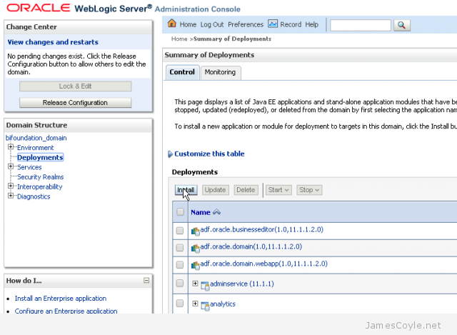
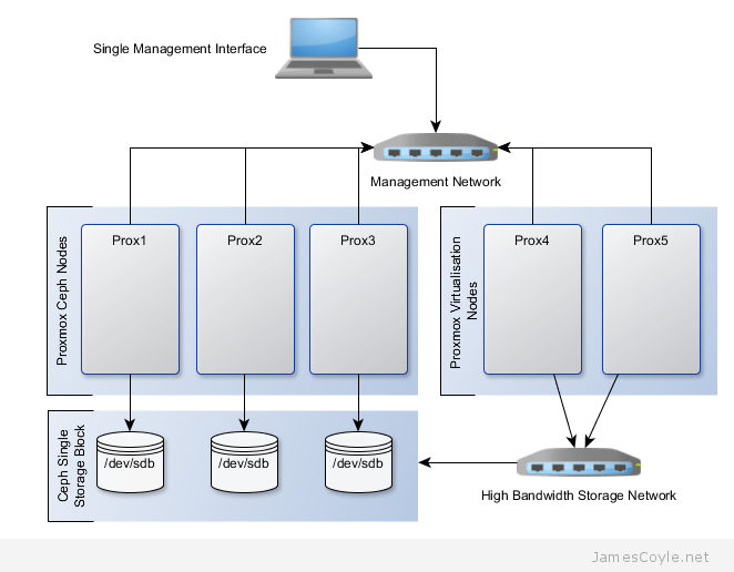
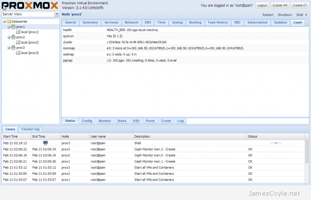
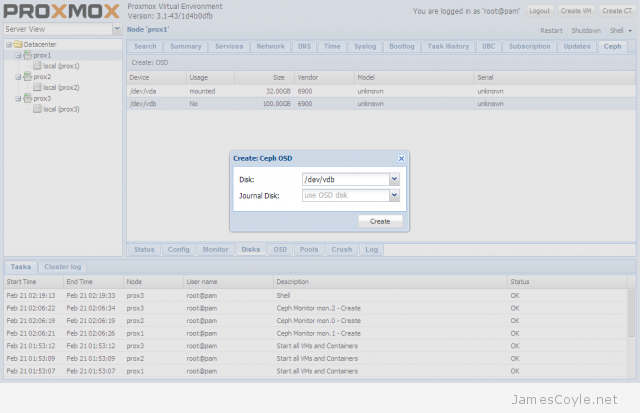
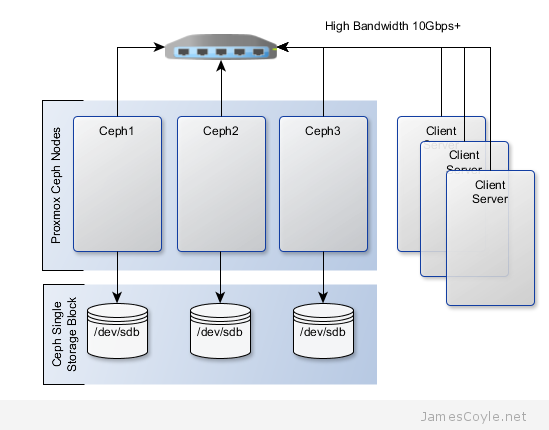
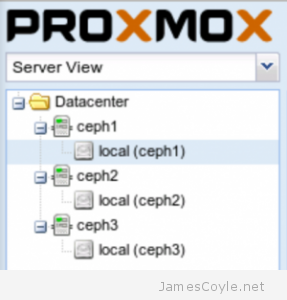
The rest of this tutorial will assume that you have three nodes which are all clustered into a single Proxmox cluster. I will refer to three host names which are all resolvable via my LAN DNS server; prox1, prox2 and prox3 which are all on the jamescoyle.net domain. The image to the left is what is displayed in the Proxmox web GUI and details all three nodes in a single Proxmox cluster. Each of these nodes has two disks configured; one which Proxmox is installed onto and provides a small ‘local’ storage device which is displayed in the image to the left and one which is going to be used for the Ceph storage. The below output shows the storage available, which is exactly the same on each host. /dev/vda is the root partition containing the Proxmox install and /dev/vdb is an untouched partition which will be used for Ceph.

root@prox1:~# fdisk -l | grep /dev/vd
Disk /dev/vdb doesn't contain a valid partition table
Disk /dev/mapper/pve-root doesn't contain a valid partition table
Disk /dev/mapper/pve-swap doesn't contain a valid partition table
Disk /dev/mapper/pve-data doesn't contain a valid partition table
Disk /dev/vda: 21.5 GB, 21474836480 bytes
/dev/vda1   *        2048     1048575      523264   83  Linux
/dev/vda2         1048576    41943039    20447232   8e  Linux LVM
Disk /dev/vdb: 107.4 GB, 107374182400 bytes

Now that I’ve set the scene, lets start to put together our Ceph cluster! Before using the new Proxmox web GUI you must run a few SSH commands to set up the initial Ceph instance.

Run the below command on all of the nodes which you will use as a Ceph server. This will download and set up the latest Ceph packages.

pveceph install

Create the Ceph config file by initialising pveceph. The Ceph config file will be created in your /etc/pve/ directory called ceph.conf. You should only run this on one node.

pveceph init --network 192.168.50.0/24

The next step is to set up the Ceph monitors for your cluster. So that you don’t have a single point of failure, you will need at least 3 monitors. You must also have an uneven number of monitors – 3, 5, 7, etc.

pveceph createmon

The rest of the configuration can be completed with the Proxmox web GUI. Log in to your Proxmox web GUI and click on one of your Proxmox nodes on the left hand side, then click the Ceph tab.

proxmox-ceph-status-tab

Next, you will add a disk to the Ceph cluster. Each disk creates to as an OSD in Ceph which is a storage object used later by the Ceph storage pool. Click on the Disks tab at the bottom of the screen and choose the disk you would like to add to the Ceph cluster. Click the Create: OSD button and click Create to create an OSD. Repeat these steps for each Proxmox server which will be used to host storage for the Ceph cluster.

ceph-create-osd

If the Create: OSD button is greyed out, it’s because the disk is not in a state where Ceph can use it. It’s likely because you have partitions on your disk. Run the fdisk command on the disk and press d to delete the partitions and w to save the changes. For example:

fdisk /dev/vdb

The last step in creating the Ceph storage cluster is to create a storage pool. Click the Pools tab and click Create. Enter the below values into the new Create Pool dialogue box:

  • Name: name to use for the storage pool.
  • Size: the number of replicas to use for a working cluster. A replica is the number of times the data is stored across nodes.
  • Min. Size: the minimum of replicas which can be used.
  • Crush RuleSet:
  • pg_num: this is the placement group count which you have to calculate based on the number os OSDs you have. To calculate your placement group count, multiply the amount of OSDs you have by 100 and divide it by the number of number of times each part of data is stored. The default is to store each part of data twice which means that if a disk fails, you won’t loose the data because it’s stored twice.For our example,3 OSDs * 100 = 300
    Divided by replicas, 300 / 2 = 150

ceph-create-pool

The Ceph storage pool is now set up and available to use for your KVM images. You can check the status of the Ceph storage pool by clicking on the Status tab.

ceph-status-screen

See my blog post on mounting Ceph storage on Proxmox.


Create a 3 Node Ceph Storage Cluster

Category : How-to

Get Social!

ceph-logoCeph is an open source storage platform which is designed for modern storage needs. Ceph is scalable to the exabyte level and designed to have no single points of failure making it ideal for applications which require highly available flexible storage.

The below diagram shows the layout of an example 3 node cluster with Ceph storage. Two network interfaces can be used to increase bandwidth and redundancy. This can help to maintain sufficient bandwidth for storage requirements without affecting client applications.

ceph-infrastructure

This example will create a 3 node Ceph cluster with no single point of failure to provide highly redundant storage. I will refer to three host names which are all resolvable via my LAN DNS server; ceph1ceph2 and ceph3 which are all on the jamescoyle.net domain. Each of these nodes has two disks configured; one which runs the Linux OS and one which is going to be used for the Ceph storage. The below output shows the storage available, which is exactly the same on each host. /dev/vda is the root partition containing the OS install and /dev/vdb is an untouched partition which will be used for Ceph.

root@ceph1:~# fdisk -l | grep /dev/vd
Disk /dev/vdb doesn't contain a valid partition table
Disk /dev/mapper/pve-root doesn't contain a valid partition table
Disk /dev/mapper/pve-swap doesn't contain a valid partition table
Disk /dev/mapper/pve-data doesn't contain a valid partition table
Disk /dev/vda: 21.5 GB, 21474836480 bytes
/dev/vda1   *        2048     1048575      523264   83  Linux
/dev/vda2         1048576    41943039    20447232   8e  Linux LVM
Disk /dev/vdb: 107.4 GB, 107374182400 bytes

Before getting started with setting up the Ceph cluster, you need to do some preparation work. Make sure the following prerequisites are met before continuing the tutorial.

You will need to perform the following steps on all nodes in your Ceph cluster. First you will add the Ceph repositories and download the key to make the latest Ceph packages available. Add the following line to a new /etc/apt/sources.list.d/ file.

vi /etc/apt/sources.list.d/ceph.list

Add the below entry, save and close the file.

deb http://ceph.com/debian-dumpling/ wheezy main

Download the key from Ceph’s git page and install it.

wget -q -O- 'https://ceph.com/git/?p=ceph.git;a=blob_plain;f=keys/release.asc' | apt-key add -

Update all local repository cache.

sudo apt-get update

Note: if you see the below code when running apt-get update then the above wget command has failed – it could be because the Ceph git URL has changed.

W: GPG error: http://ceph.com wheezy Release: The following signatures couldn't be verified because the public key is not available: NO_PUBKEY 7EBFDD5D17ED316D

Run the following commands on just one of your Ceph nodes. I’ll use ceph1 for this example. Update your local package cache and install the ceph-deploy command.

apt-get install ceph-deploy -y

Create the first Ceph storage cluster and specify the first server in your cluster by either hostname or IP address for [SERVER].

ceph-deploy new [SERVER]

For example

ceph-deploy new ceph1.jamescoyle.net

Now deploy Ceph onto all nodes which will be used for the Ceph storage.  Replace the below [SERVER] tags with the host name or IP address of your Ceph cluster including the host you are running the command on. See this post if you get a key error here.

ceph-deploy install [SERVER1] [SERVER2] [SERVER3] [SERVER...]

For example

ceph-deploy install ceph1.jamescoyle.net ceph2.jamescoyle.net ceph3.jamescoyle.net

Install the Ceph monitor and accept the key warning as keys are generated. So that you don’t have a single point of failure, you will need at least 3 monitors. You must also have an uneven number of monitors – 3, 5, 7, etc. Again, you will need to replace the [SERVER] tags with your server names or IP addresses.

ceph-deploy mon create [SERVER1] [SERVER2] [SERVER3] [SERVER...]

Example

ceph-deploy mon create ceph1.jamescoyle.net ceph2.jamescoyle.net ceph3.jamescoyle.net

Now gather the keys of the deployed installation, just on your primary server.

ceph-deploy gatherkeys [SERVER1]

Example

ceph-deploy gatherkeys ceph1.jamescoyle.net

It’s now time to start adding storage to the Ceph cluster. The fdisk output at the top of this page shows that the disk I’m going to use for Ceph is /dev/vdb, which is the same for all the nodes in my cluster. Using Ceph terminology, we will create an OSD based on each disk in the cluster. We could have used a file system location instead of a whole disk but, for this example, we will use a whole disk. Use the below command, changing [SERVER] to the name of the Ceph server which houses the disk and [DISK] to the disk representation in /dev/.

ceph-deploy osd --zap-disk create [SERVER]:[DISK]

For example

ceph-deploy osd --zap-disk create ceph1.jamescoyle.net:vdb

If the command fails, it’s likely because you have partitions on your disk. Run the fdisk command on the disk and press d to delete the partitions and w to save the changes. For example:

fdisk /dev/vdb

Run the osd command for all nodes in your Ceph cluster

ceph-deploy osd --zap-disk create ceph2.jamescoyle.net:vdb
ceph-deploy osd --zap-disk create ceph3.jamescoyle.net:vdb

We now have to calculate the number of placement groups (PG) for our storage pool. A storage pool is a collection of OSDs, 3 in our case, which should each contain around 100 placement groups. Each placement group will hold your client data and map it to an OSD whilst providing redundancy to protect against disk failure.

To calculate your placement group count, multiply the amount of OSDs you have by 100 and divide it by the number of number of times each part of data is stored. The default is to store each part of data twice which means that if a disk fails, you won’t loose the data because it’s stored twice.

For our example,

3 OSDs * 100 = 300
Divided by replicas, 300 / 2 = 150

Now lets create the storage pool! Use the below command and substitute [NAME] with the name to give this storage pool and [PG] with the number we just calculated.

ceph osd pool create [NAME] [PG]

For example

ceph osd pool create datastore 150
pool 'datastore' created

You have now completed the set up for the Ceph storage pool. See my blog post on mounting Ceph storage on Proxmox.


How to Cluster Proxmox

Category : How-to

Get Social!

proxmox logo grad

Clustering is a technique to group together multiple machines or devices providing common parameters, such as storage, over all machines in the cluster. Proxmox can be clustered to provide a common interface to control all machines in the cluster.

Automatic failover of machines can also be achieved with a Proxmox cluster however this requires significant setup and it not available out of the box. I will discuss VM failover in a future blog post.

Create a new Cluster

To join one or more nodes to a Proxmox cluster we must first create a cluster on one of the machines. Run the below command on your first Proxmox node and replace [CLUSTER_NAME] with a name for your cluster.

pvecm create [CLUSTER_NAME]

Check the status of a Cluster

Once a cluster is created, you can check the status using the status command.

pvecm status

You can use the nodes command to view all nodes in the cluster.

pvecm nodes

Add a new Node to the Cluster

Adding a new node to a Proxmox cluster is easy and only requires the hostname or IP address of the primary cluster node. It is highly recommended to use a hostname or DNS entry over an IP address to shield any IP address changes.

On a non-clustered node, log in and run the pvecm add command and specify the IP address or hostname. You can use the IP address or hostname of any already clustered Proxmox node.

pvecm add [HOSTNAME_OF_CLUSTER]

You must not have any virtual machines/ OpenVZ containers running on the node which you are adding to the cluster. All nodes should also be running the same component versions of Proxmox to ensure compatibility.


Visit our advertisers

Quick Poll

Are you using Docker.io?

Visit our advertisers